The phenomenon of electrical resistance, a fundamental property of materials used in wires, significantly influences what happens when electricity courses through them. Ohm’s Law, a cornerstone principle governing electrical circuits, dictates the relationship between voltage, current, and resistance in these wires. Understanding how these interactions occur, particularly when working with devices like a multimeter to measure current and voltage, helps to illuminate what happens to wires when electricity flows through them. Exploring these principles is essential for anyone interested in electrical engineering, from student like Nikola Tesla, to professional engineers.
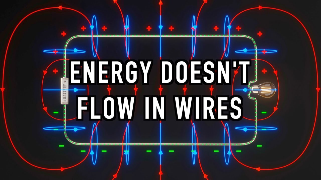
Image taken from the YouTube channel Veritasium , from the video titled The Big Misconception About Electricity .
Unveiling the Secrets of Electricity in Wires
Electricity. It powers our homes, fuels our industries, and connects us to the world. But how does this invisible force travel from power plants to our devices? The answer lies, quite literally, in the wires that snake through our walls and across the landscape. This exploration delves into the heart of what happens when electricity courses through these vital conductors.
At its most basic, electricity is the flow of electric charge. This flow, known as electric current, requires a pathway, and in most everyday applications, that pathway is a wire. Wires, typically made of metals like copper or aluminum, act as conduits, allowing electrons to move relatively freely.
Electricity: The Unseen Force
From the moment we flip a light switch to the continuous hum of our refrigerators, we are constantly interacting with electricity. Our dependence on this energy source is undeniable. This dependence highlights the critical role of wires in our modern infrastructure. Without these connections, our technological world would grind to a halt.
Understanding the Fundamentals
Before we dive deep into the effects of electricity on wires, it’s essential to touch upon a few fundamental concepts. These concepts are essential for understanding the flow of electricity and the resulting phenomena.
Voltage, often described as electrical potential difference, is the driving force that pushes electrons through the wire. Current measures the rate at which these electrons flow. Resistance, on the other hand, is the opposition to this flow, hindering the movement of electrons and affecting the overall behavior of the circuit.
These three quantities—voltage, current, and resistance—are inextricably linked. Their interplay governs everything that happens within an electrical circuit.
The Goal: Illuminating Electrical Effects
The purpose of this analysis is to illuminate the various effects that electricity has on the wires through which it passes. From the generation of heat to the creation of electromagnetic fields, we will explore the science behind these phenomena. We will also look at the practical implications and potential dangers associated with the flow of electricity in wires. Our focus is to understand what happens to wires as they dutifully transport electrical energy to power our world.
The Players: Essential Elements of Electrical Flow
Now that we’ve set the stage, it’s time to meet the key players. Understanding the fundamental components and properties involved in electrical conduction is crucial before we can truly grasp the effects of electricity flowing through wires. Let’s introduce the essential entities that make this phenomenon possible.
Defining Electricity and Its Nature
At its core, electricity is the flow of electric charge. This charge is carried by subatomic particles, most notably electrons. We experience electricity in countless forms, from static cling to the power that illuminates our homes. It’s a fundamental force of nature, and understanding its nature is paramount.
Wires as Conductors: The Electrical Highway
Wires act as the primary pathway for electrical current in most practical applications. Typically made of metals like copper or aluminum, they are chosen for their ability to conduct electricity efficiently. The atomic structure of these materials allows electrons to move relatively freely. This ease of movement is what defines a good conductor.
Key Electrical Quantities
To further understand the flow, we have to introduce three important metrics.
Current (Ampere): The River of Electrons
Current, measured in Amperes (A), quantifies the rate at which electric charge flows through a circuit. Think of it as the amount of water flowing through a pipe. The higher the current, the more electrons are passing a given point per unit of time.
Voltage (Volt): The Electrical Push
Voltage, measured in Volts (V), represents the electrical potential difference between two points in a circuit. It’s the driving force that pushes electrons along the wire. This potential difference creates an electric field, which propels the charged particles.
Resistance (Ohm): The Obstacle to Flow
Resistance, measured in Ohms (Ω), opposes the flow of current in a circuit. It’s like friction in a mechanical system. Resistance arises from the interactions of electrons with the atoms within the conducting material.
The Microscopic View: Electrons and Atoms
Electricity, at its most fundamental level, involves the interaction of electrons and atoms. Atoms, the building blocks of matter, consist of a nucleus surrounded by orbiting electrons. In conductive materials, some electrons are loosely bound to their atoms. These loosely bound electrons are free to move throughout the material when a voltage is applied.
Conductors vs. Insulators: Choosing the Right Material
Materials are broadly classified as either conductors or insulators based on their ability to conduct electricity. Conductors, like copper and aluminum, have a large number of free electrons. Insulators, on the other hand, like rubber and plastic, have very few free electrons and thus resist the flow of electricity. This difference is vital for safely directing and controlling electrical current. Insulators are used to coat the conductors for safety.
Electricity coursing through wires is more than just a silent flow; it’s a dynamic process that creates tangible effects. One of the most readily observable is the generation of heat. But how does this happen?
Heating Up: The Thermal Effects of Electrical Current
When electrons, carrying electrical charge, move through a wire, they encounter resistance. This resistance is inherent in the material of the wire itself, acting as a kind of obstacle course for the electrons.
The Conversion of Electrical Energy to Heat
As electrons collide with the atoms within the wire’s structure, they transfer some of their kinetic energy. This energy transfer manifests as increased atomic vibration, which we perceive as heat. In essence, electrical energy is being converted into thermal energy due to the resistance the wire offers to the flow of current.
This phenomenon is known as Joule heating, also sometimes referred to as resistive or Ohmic heating. It’s a fundamental principle that governs the behavior of electrical circuits and has both useful applications and potential hazards.
Joule’s Law: Quantifying Heat Generation
The amount of heat generated is directly related to the current flowing through the wire and the resistance of the wire. This relationship is precisely defined by Joule’s Law, which can be expressed as:
P = I²R
Where:
- P is the power dissipated as heat (measured in Watts)
- I is the current flowing through the wire (measured in Amperes)
- R is the resistance of the wire (measured in Ohms)
This equation highlights a critical point: the heat generated increases exponentially with the current. Doubling the current results in four times the heat.
Factors Influencing Heat Generation
Several factors influence the amount of heat generated in a wire:
- Current: As Joule’s Law dictates, a higher current results in greater heat production.
- Resistance: A wire with higher resistance will generate more heat for the same current.
- Wire Material: Different materials have different resistivities. Copper and aluminum are commonly used due to their low resistance, while other materials like nichrome are specifically chosen for heating elements because of their higher resistance.
- Wire Gauge: Thinner wires have higher resistance than thicker wires. This is because the electrons have less space to move, leading to more collisions and thus more resistance. Wire gauge is a standard measure of wire thickness.
Everyday Applications of Joule Heating
Joule heating isn’t just a theoretical concept; it’s the principle behind many common devices:
- Toasters and Electric Heaters: These appliances utilize high-resistance wires (often made of nichrome) to generate heat when current passes through them.
- Incandescent Light Bulbs: While inefficient, incandescent bulbs produce light by heating a filament to a very high temperature until it glows.
Potential Dangers of Overheating
While Joule heating has its uses, uncontrolled heat generation can be dangerous:
- Fire Hazards: Excessive heat can ignite surrounding materials, leading to fires. This is why proper wiring and circuit protection are essential.
- Insulation Damage: Overheating can degrade the insulation around wires, exposing the conductor and creating a risk of electric shock or short circuits.
- Melting: In extreme cases, a wire can overheat to the point of melting, causing a complete circuit failure and potentially starting a fire.
The Importance of Proper Wire Sizing
To prevent overheating, it’s crucial to use the correct wire size for the intended application. The National Electrical Code (NEC) provides guidelines for the appropriate wire gauge based on the expected current draw of a circuit. Using a wire that is too thin can lead to excessive heat generation and increase the risk of fire.
Choosing the right wire and implementing appropriate safety measures are crucial for harnessing electricity safely and effectively.
Electromagnetic Fields: The Invisible Force Fields
While the heating of a wire is a readily apparent consequence of electrical current, there exists a more subtle, invisible phenomenon occurring simultaneously: the generation of electromagnetic fields (EMF). These fields, radiating outwards from any current-carrying wire, represent a fundamental interplay between electricity and magnetism.
The Origin of Magnetic Fields
Whenever electric charge is in motion—that is, when current flows—it creates a magnetic field in the space surrounding it. This is not a theoretical concept; it’s a directly observable consequence of the fundamental laws of physics. Imagine a wire as a highway for electrons. As these electrons surge along, they generate a circular magnetic field around the wire, like ripples in a pond around a moving boat.
Understanding Electromagnetic Fields
The term "electromagnetic field" encompasses both the electric field and the magnetic field generated by a charged particle. In the case of a wire, the constant flow of current creates a static, but continuous, magnetic field. Changing electric fields also generate magnetic fields, and vice versa; this is the essence of electromagnetism.
Strength and Direction: Factors Influencing the Magnetic Field
The strength of the magnetic field is directly proportional to the magnitude of the current flowing through the wire. A higher current translates to a stronger magnetic field. Furthermore, the distance from the wire impacts the field strength; the further you move away from the wire, the weaker the magnetic field becomes.
The direction of the magnetic field is determined by the direction of the current flow. This relationship is governed by the right-hand rule: If you point your right thumb in the direction of the current, your fingers will curl in the direction of the magnetic field.
Applications of Electromagnetism: From Motors to Transformers
The principle of electromagnetism is the cornerstone of numerous technologies that underpin modern life.
Electromagnets, for instance, are created by winding a coil of wire around a ferromagnetic core. When current flows through the coil, it generates a strong magnetic field, which can be turned on and off by controlling the current. These are used extensively in lifting magnets, electric doorbells, and many other devices.
Electric motors utilize the interaction between magnetic fields created by current-carrying wires and permanent magnets to generate rotational motion.
Transformers rely on electromagnetic induction to transfer electrical energy between circuits with different voltage levels. They use two coils of wire and the magnetic field created in one coil induces a current in the other coil, facilitating the efficient transmission of electricity over long distances.
EMF Exposure: A Note of Caution
The presence of EMFs in our environment has led to some debate regarding potential health effects. Some studies have suggested a possible link between exposure to strong EMFs and certain health conditions. It’s important to note that the scientific consensus on this topic is still evolving, and more research is needed to fully understand the long-term effects of EMF exposure. Most household EMFs are considered low-level and within acceptable safety guidelines, but prudence and awareness are always advisable.
Acknowledging Faraday’s Insight
Our understanding of electromagnetism owes a great deal to the pioneering work of Michael Faraday. His experiments in the 19th century demonstrated the connection between electricity and magnetism, laying the foundation for the development of countless technologies that shape our world today. Faraday’s discoveries continue to inspire and guide scientists and engineers as they explore the frontiers of electromagnetism.
Safety First: Protecting Against Electrical Hazards
Having explored the fascinating, albeit invisible, world of electromagnetic fields generated by electrical currents, it becomes paramount to shift our focus to a critical aspect: safety. Electricity, while an indispensable tool, presents significant hazards if not handled with the utmost care and respect. A comprehensive understanding of potential dangers and preventative measures is essential for anyone interacting with electrical systems, whether in a domestic or professional setting.
Understanding Short Circuits and Overloads
Two of the most common and dangerous electrical faults are short circuits and overloads. These conditions arise when the intended path of electrical current is disrupted, leading to potentially catastrophic consequences.
A short circuit occurs when electricity finds an unintended, low-resistance path back to its source, bypassing the intended load. This can happen due to damaged insulation, loose wiring, or accidental contact between conductors.
The sudden surge of current can cause rapid heating of wires, leading to insulation melting, fires, and even explosions.
An overload, on the other hand, happens when too much current is drawn through a circuit. This can occur when multiple appliances are connected to a single outlet or when a device malfunctions and draws excessive power.
Similar to a short circuit, an overload causes wires to overheat, increasing the risk of fire. Distinguishing between these two scenarios and recognizing their potential for harm is the first step in preventing electrical accidents.
The Role of Fuses and Circuit Breakers
Fortunately, we have safety devices designed to protect electrical systems from the dangers of short circuits and overloads: fuses and circuit breakers. These devices act as sentinels, monitoring the flow of current and interrupting the circuit when dangerous conditions are detected.
Fuses contain a thin wire that melts and breaks the circuit when the current exceeds a predetermined level. They are a one-time-use device and must be replaced after blowing.
Circuit breakers, on the other hand, are resettable switches that automatically trip and interrupt the circuit in response to an overload or short circuit. They can be reset manually after the fault has been corrected.
Both fuses and circuit breakers are rated for specific current levels, and it is crucial to use the correct rating for each circuit. Using a fuse or circuit breaker with a higher rating than intended can defeat its protective function and create a significant fire hazard.
Grounding: A Vital Safety Measure
Grounding provides a safe path for stray electrical current to flow back to the source, preventing electric shock. A grounding wire connects the metal enclosures of appliances and electrical equipment to the earth, providing a low-resistance path for current to flow in the event of a fault.
Without grounding, a person touching a faulty appliance could become part of the circuit, resulting in a potentially lethal electric shock.
Ground Fault Circuit Interrupters (GFCIs) are even more sensitive safety devices that quickly interrupt the circuit when they detect a difference in current between the hot and neutral wires, indicating a potential ground fault. GFCIs are commonly used in bathrooms, kitchens, and outdoor outlets where the risk of electric shock is higher.
Adhering to Electrical Codes
Electrical codes, such as the National Electrical Code (NEC) in the United States, provide a comprehensive set of safety standards for electrical installations. These codes cover everything from wire sizing and insulation requirements to the proper installation of outlets, switches, and lighting fixtures.
Compliance with electrical codes is essential to ensure the safety of electrical systems and prevent electrical hazards. Local building inspectors enforce these codes, ensuring that electrical work is performed safely and correctly.
Testing Equipment and Professional Assistance
Using testing equipment, such as a multimeter, is crucial for diagnosing electrical problems and verifying the safety of electrical circuits. A multimeter can measure voltage, current, and resistance, allowing you to identify potential faults and ensure that circuits are properly wired.
However, it is important to use testing equipment safely and to have a thorough understanding of electrical principles before attempting any electrical work.
When in doubt, always seek the assistance of a qualified electrician. Electrical work can be dangerous, and it is best left to professionals who have the training, experience, and equipment necessary to perform the work safely and correctly.
Prioritizing safety, understanding the risks, and utilizing appropriate safety measures are crucial in navigating the world of electricity without incident.
Having armed ourselves with the knowledge of safety mechanisms designed to mitigate electrical hazards, we now turn our attention to the very nature of the electricity that powers our lives and how it journeys from power plants to our homes.
Power Delivery: AC vs. DC and the Power Grid
The electricity we use daily comes in two primary forms: Alternating Current (AC) and Direct Current (DC). Understanding the fundamental differences between these is crucial to grasping how our power grid functions.
Alternating Current (AC) Explained
Alternating Current is characterized by its cyclical change in direction. Electrons flow first in one direction, then reverse and flow in the opposite direction. This reversal happens at a specific frequency, typically 50 or 60 Hertz (Hz), meaning the current changes direction 50 or 60 times per second.
This ability to easily change voltage levels using transformers makes AC the preferred choice for long-distance power transmission. Nikola Tesla championed AC power, recognizing its superiority for large-scale distribution, a vision that shaped the modern electrical grid.
Direct Current (DC) Explained
Direct Current, on the other hand, flows in one direction only. Batteries are a common source of DC power, providing a steady and constant flow of electrons.
While DC is suitable for powering electronic devices and is gaining traction in localized energy systems (like solar panel installations), it is not efficient for long-distance transmission at lower voltages due to significant energy loss along the way.
The Power Grid: A Marvel of Engineering
The power grid is a complex network of power plants, transmission lines, and distribution systems that work in concert to deliver electricity to consumers. Power generation typically occurs at large-scale power plants using various sources, including fossil fuels, nuclear energy, hydroelectric power, and renewable energy sources like solar and wind.
The generated electricity is then fed into the transmission grid, which consists of high-voltage power lines that transport electricity over long distances to substations.
The Role of Transformers
Transformers are essential components of the power grid, enabling the efficient transmission of electricity over long distances. They leverage the principles of electromagnetic induction to step up or step down voltage levels.
Stepping Up Voltage for Efficient Transmission
At the power plant, transformers step up the voltage to extremely high levels (e.g., hundreds of thousands of volts). This reduces the current flowing through the transmission lines, minimizing energy loss due to resistance.
Higher voltage means lower current for the same amount of power, and since power loss in a wire is proportional to the square of the current (I²R), minimizing current drastically reduces losses.
Stepping Down Voltage for Safe Distribution
Once the electricity reaches a substation near a city or town, transformers step down the voltage to lower, safer levels suitable for distribution to homes and businesses.
Further voltage reductions occur at local transformers, often seen as cylindrical containers mounted on utility poles, before the electricity finally reaches our outlets. This cascading voltage reduction ensures safe and usable electricity delivery to end users.
Electricity & Wires: Frequently Asked Questions
Got questions about how electricity and wires work? Here are some common ones answered simply.
Why do wires get warm when electricity flows through them?
Wires resist the flow of electricity. This resistance converts some of the electrical energy into heat. That’s why wires warm up when electricity flows through them. You need to know what happens to wires when electricity flows through them to understand this process.
What type of wire is safest to use in my home?
Copper wires are generally the safest and most common type for home wiring. They are good conductors of electricity and relatively resistant to corrosion. Also, the insulation around the wire is critical for safety.
Can electricity flow through a wire that’s cut or broken?
No, electricity cannot flow through a wire that is completely cut or broken. The break creates an open circuit, stopping the flow. Therefore, electricity stops flowing when there isn’t a continuous path.
How does the thickness of a wire affect how much electricity it can carry?
Thicker wires can carry more electricity than thinner wires. A thicker wire offers less resistance to the flow of electricity, allowing more current to pass through without overheating. It’s crucial to know what happens to wires when electricity flows through them, including how the wire size affects its capacity.
So, next time you flip a switch, remember what we covered about know what happens to wires when electricity flows through them. Pretty fascinating stuff, right? Keep exploring, and stay charged!